![]()
MY2024> Ford
BusBuster PRO
Homologation and Trailer Interface
Installation Manual
BB-0101
Version: v2026.1
Introduction
This manual explains how to install the BusBuster PRO interface in a Ford F-150 model year 2024 and newer.
This interface supports the homologation of the vehicle.
It also provides the necessary outputs for a full EU trailer setup.
The interface adjusts the vehicle’s coding to match the converted navigation system,
changed lighting, and trailer configuration, and stores these settings.
These settings are retained even when the vehicle’s configuration is restored using factory tools.
After installation and switching languages, it will still show the message
“Some languages are not supported on one or more systems”.
You can ignore this message, and it is still possible to switch the languages on the radio.
Unfortunately, the IPC will not switch languages if it does not support them.
Functions
- Enable switching of the language.
- Perform necessary recoding for navigation conversion.
- Perform necessary recoding to adapt the lights to EU specs.
- Protect the coding against factory resets.
- Enable full navigation on limited/online-nav vehicles.
- Enable rear fog light control via the OEM light switch.
- Add outputs to complement the OEM trailer plug for a full 13-pin EU trailer.
- Provide fault detection for trailer turn signals.
- OEM trailer detection. (Disable PDC, lane warnings, vehicles rear foglight etc)
- Ensure compatibility with our trailer harness for quick installation.
Installation
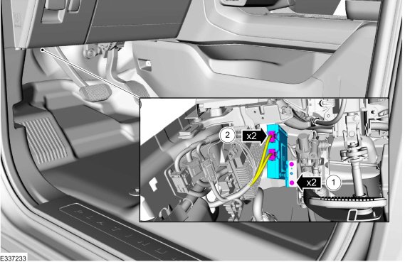
TRM Connections
- Remove the black (lower) connector from the TRM module.
- Connect the vehicle’s connector to the
supplied T-harness.
- Connect the other end of the T-harness
back into the TRM module.
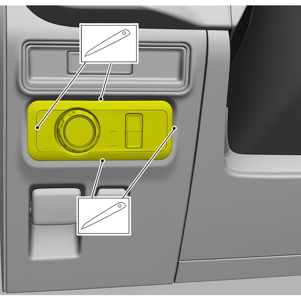
Light Switch Connections
Optional: Only required if adding a rear fog light.
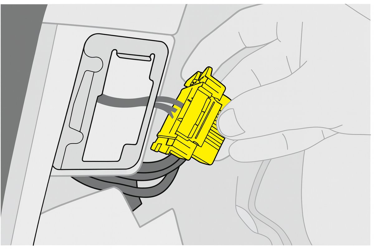
- Use plastic trim removal tools to remove the light switch.
- Unplug the connector from the back.
- Connect the vehicle’s connector to the
supplied T-harness.
- Connect the other end of the T-harness
back into the light switch. - If the OEM light switch does not have a front fog button,
place the supplied sticker to indicate the switch function.
OBD Connections
- Remove the OBD socket from the metal frame.
- Connect the vehicle’s connector to the
supplied T-harness.
- Mount the other end of the T-harness
back into the metal frame.
Lighting Adjustment
The following optional changes will move the turn signal to the reverse lights.
You should also change the color of the reverse lights by swapping the lamp or inserting a colored filter.
A replacement reverse light can be connected to the OEM trailer plug
or to the reverse light output on the optional trailer harness.
If you do NOT want to use this feature, disable it in the interface settings
with the BusBuster Loader PC program.
If left enabled, the vehicle will display lighting error messages.
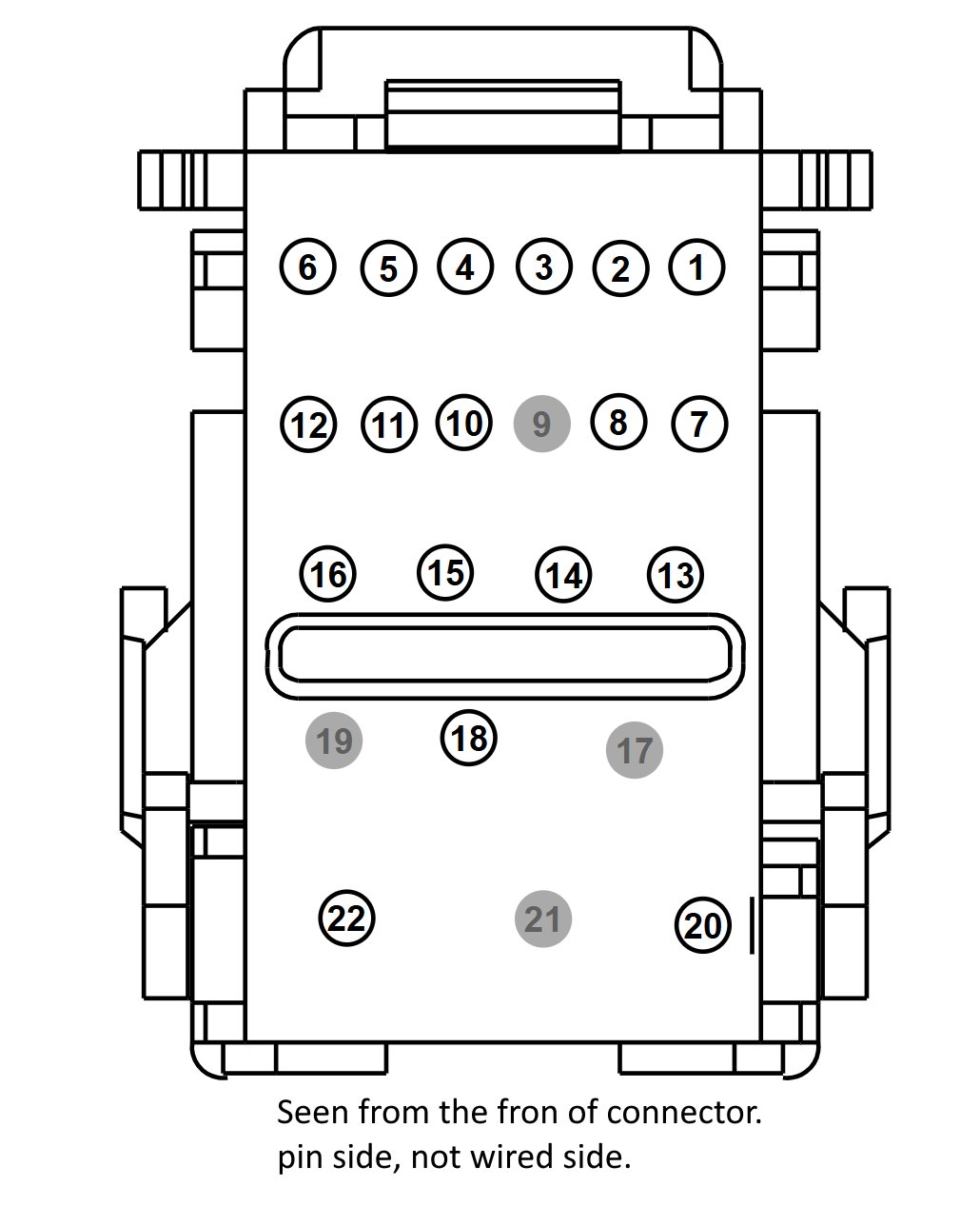
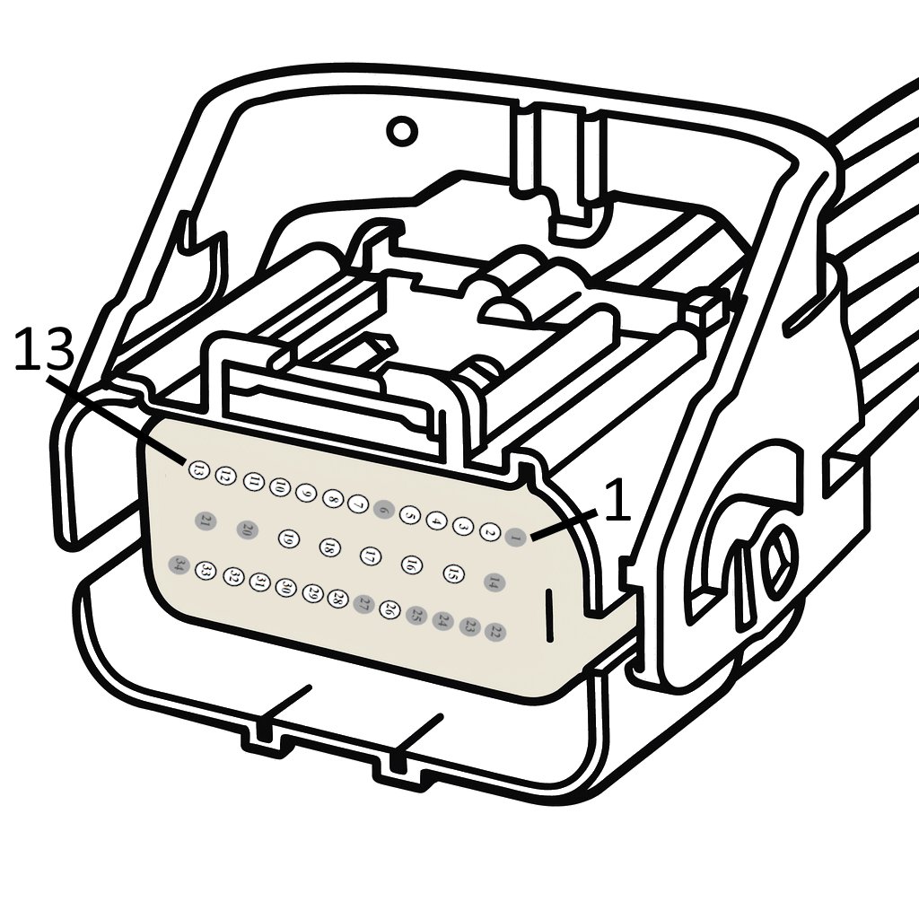
BCM Connections
Remove the passenger-side side panel.
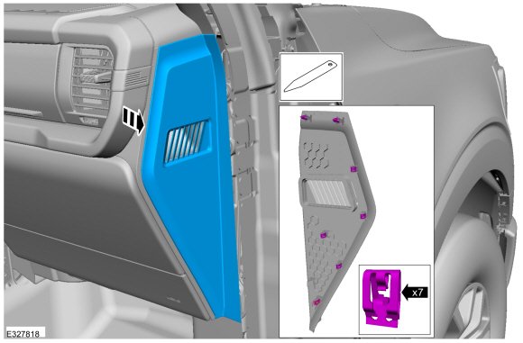
Remove the passenger-side doorstep panel.
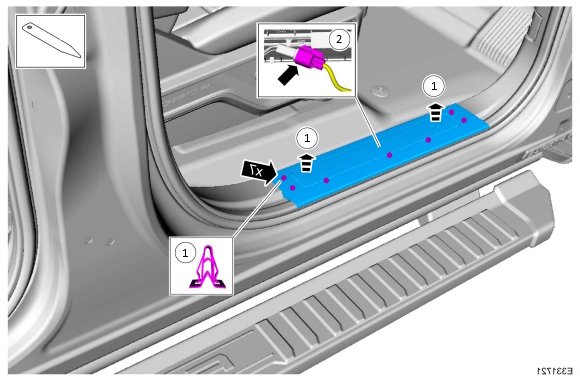
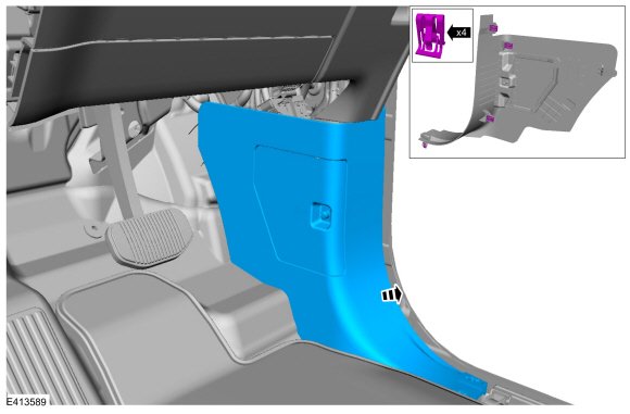
Remove the passenger-side kick panel.
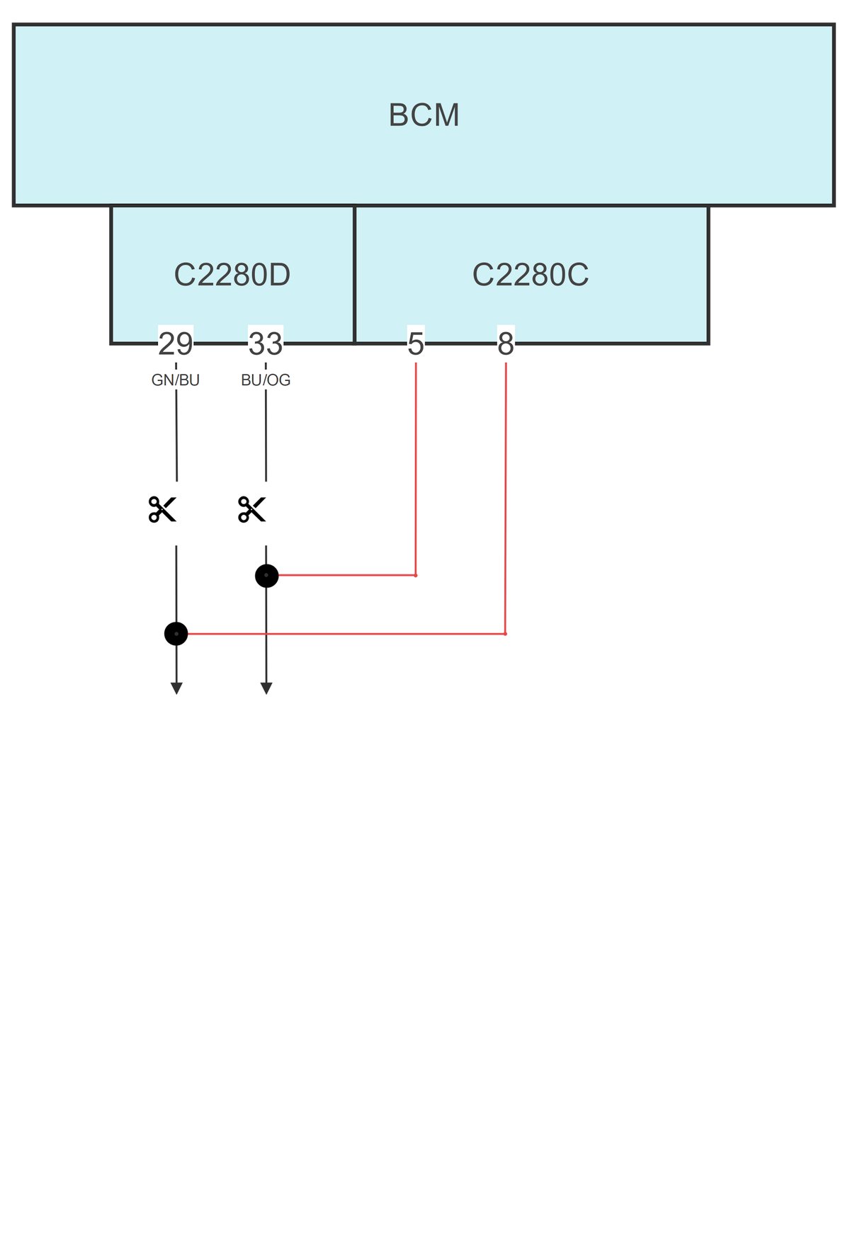
Unplug the C2280C and C2280D plugs.
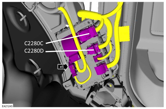
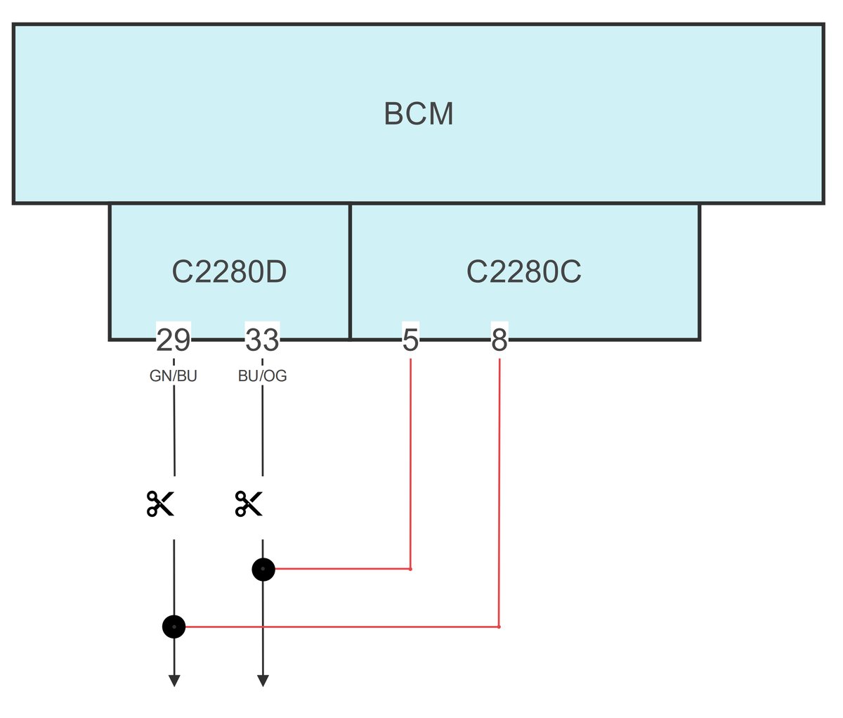
Cut the following wires from C2280D:
- Pin 33 - Blue/Orange
- Pin 29 - Green/Blue
Connect the supplied short 2-wire loom.
| C2280D | |
|---|---|
| Green | Pin 29 - Green/Blue, car side |
| White | Pin 33 - Blue/Orange, car side |
If these pins are not wired, install wires from the C2280C (next step) connector to the tail lights.
Route the 2-wire loom from the previous step to connector C2280C.
Plug in the 2 pins.
| C2280C | |
|---|---|
| Green | Pin 8 |
| White | Pin 5 |
Check if pin 4 is wired. If not, install a wire from here to the rear fog light.
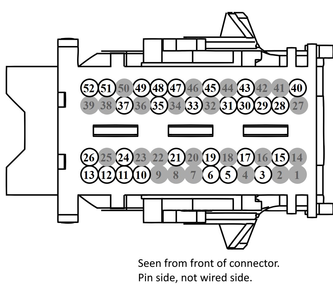
Connection diagram:
Reinstall the removed trim around the BCM.
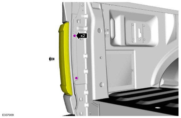
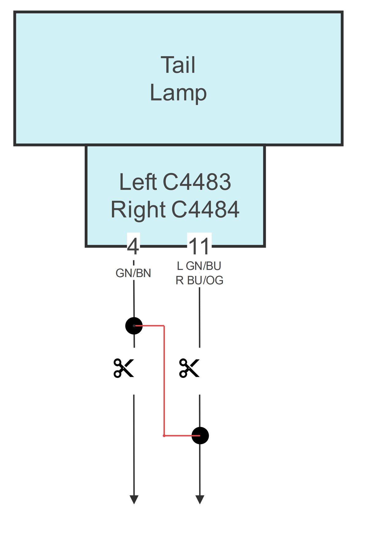
Tail Lamp Connections
Remove the tail lights by unscrewing the 2 screws.
Unplug the connectors.
Cut the following wires from the tail lamp connector:
| Left Lamp |
|---|
| Pin 11 - Green/Blue |
| Pin 4 - Green/Brown |
| Right Lamp |
|---|
| Pin 11 - Blue/Violet |
| Pin 4 - Green/Brown |
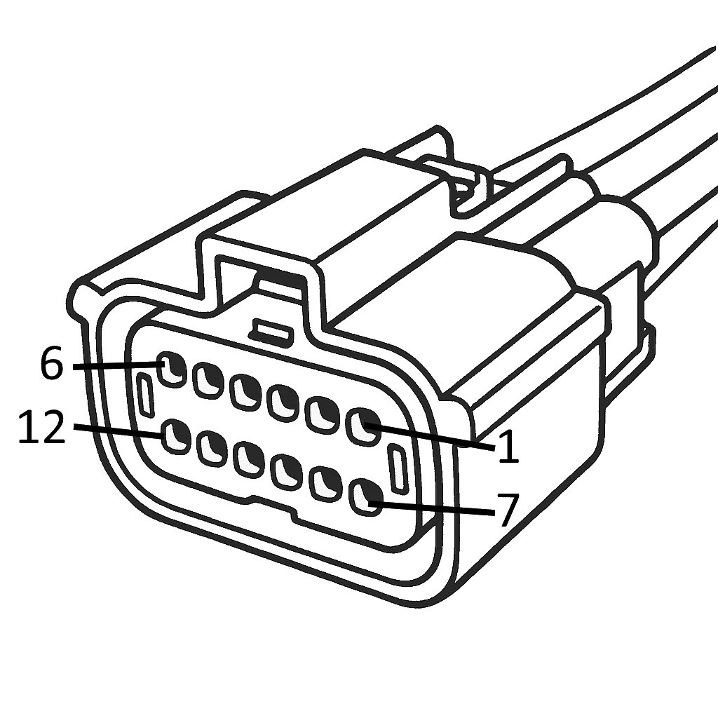
For both lamps:
- Connect the car-side pin 11 wire to the connector pin 4 wire.
- Isolate both loose wire ends.
- Reinstall the lamps.
Rear Fog Lamp Connection
The rear fog signal can be found on connector C423, just above the spare tire.
Lower the spare tire for easier access.
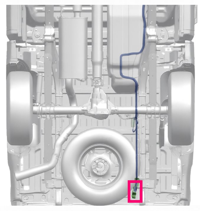
Connect the added rear fog light to pin 5 (White/Blue) of the C423 connector.
Note:
In some vehicles this pin may not be wired.
If so, install a wire to the BCM.
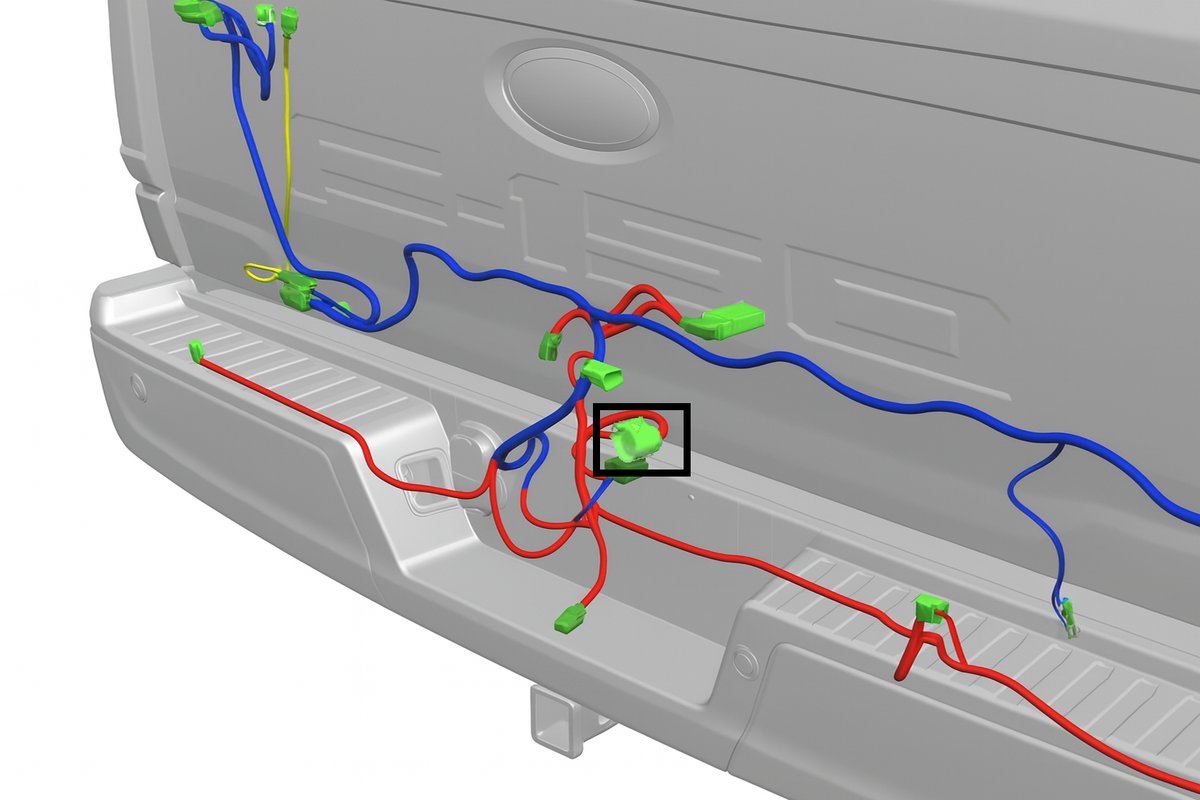
Trailer Harness
The optional trailer harness can significantly reduce installation time.
The harness connects directly to the connector behind the OEM trailer socket.
The other end contains loose pins that can be inserted into the free cavities of the BusBuster connector.
This allows for a fully functional EU trailer socket without cutting or soldering any wires.
Mounting Trailer Harness
- Unplug the connector from the rear of the OEM trailer socket.
- Connect the trailer harness in between.
- Mount the 13 EU trailer socket.
- Route the cable to below the rear bench,
on the driver side. - Remove the floor console below the rear seats,
by removing the 4 bolts behind the caps. - Remove the rear driver side doorstep panel.
- Position the carpeting away from the work area.
- Drill a hole in the plastic plate and feed the cable through.
- Ensure the cable passage is watertight.
- Route the cable to the BusBuster interface near the TRM module.
- Ensure the cable is securely mounted,
and kept away from exhaust heat.
Connecting to BusBuster
Insert the 4 trailer harness wires into the BusBuster connector as shown below.
| PIN | Color | Function |
|---|---|---|
| 1 | Red* | +12V Input |
| 2 | Grey | Trailer ACC output |
| 3 | Blue | Trailer fog light |
| 4 | Black* | GND input |
| 5 | Yellow | Trailer turn signal (left) |
| 6 | Green | Trailer turn signal (right) |
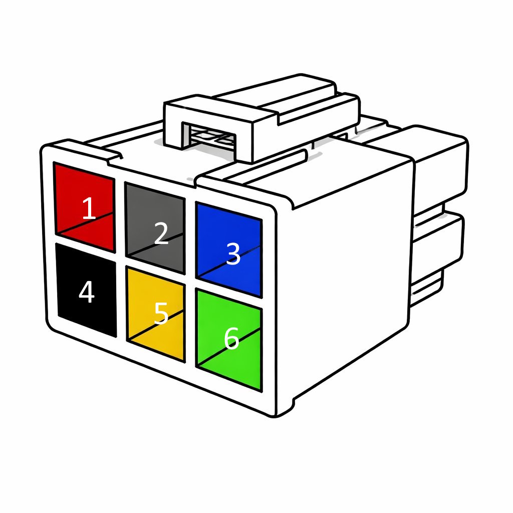
Note:
The red and black wires are pre-installed in the BusBuster connector.
The two additional loose wire outputs near the 7-pin socket provide an output for an additional vehicle reverse light.
This is typically used when the OEM reverse lights are repurposed as turn signals.
If the trailer harness is not used,
the connections can be wired manually.
Terminal P/N: MOLEX 76823-0322.
Wrap-Up
Ensure all connections are secure and neatly finish the wiring with tape or heat shrink.
Mount the BusBuster using the supplied double-sided tape pad
or with cable ties.
Erase all DTCs that may have been set during installation.
Verify all interface functions.
Usage
The interface makes almost all functions behave as if they were OEM.
The added rear fog light can be controlled in two ways:
- By the front fog switch (off → F on → F+R on → F on → off)
- By pressing the dimming-up and dimming-down switches at the same time.
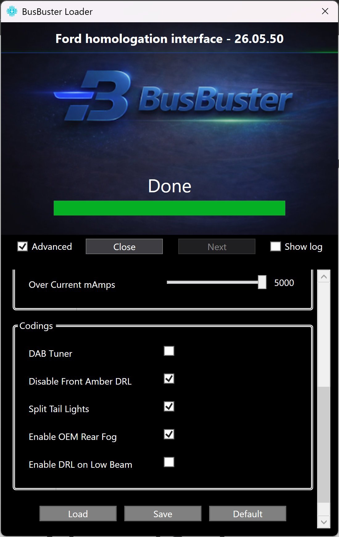
Programming
With the BusBuster Loader PC software,
you can update the interface to the latest firmware.
It also allows you to perform various specific codings for the interface.
To do so, open the software.
After it has flashed the interface, click Advanced.
Change the settings as required and click Write to save them to the interface.
You can also save and load settings if you want to reuse them for multiple cars.
Advanced Settings
| General | Default | Description |
|---|---|---|
| Enable Fault Detection | ON | Enables or disables trailer over- and under-current detection. |
| ACC Switch Selection | ACC | Selects when pin 10 (switched power) is powered. |
| ACC Time Add | 0 min | Optionally keep it powered for extra time after turning off the car. |
| Codings | Default | Description |
|---|---|---|
| DAB Tuner | OFF | Enable only if the OEM ACM module has been replaced with an EU DAB tuner. |
| Disable Front Amber DRL | ON | Disables the amber marker lights in the front headlights, to comply with EU lighting regulations. |
| Split Tail Lights | ON | Moves the rear turn signals from the brake lights to a separate output. |
| Enable OEM Rear Fog | ON | Enables control and output for the rear fog light (requires LIN connection to the light switch). |
| Enable DRL on Low Beam | OFF | Uses the low beam headlights as DRL, keeping them on while driving. |
| Disables exhaust mode button | OFF | (RAPTOR ONLY) Disables the exhaust mode button, as may be required by some countries. |
Cheat Sheet
| BCM | C2280C | C2280D |
|---|---|---|
 |
|
|
| Tail Lamp | Tail Lamp Connector |
|---|---|
|
|